 TR
TR EN
EN
A successful industrial coating line is planned by evaluating product flow, process stages, capacity and factory layout as one complete system—not simply by selecting a booth, oven or conveyor. Choosing equipment before the products, coating system, production targets and existing plant conditions are clearly defined can lead to bottlenecks, energy losses and costly modifications.
For an accurate technical quotation, product dimensions and weights, material and surface condition, hourly and annual capacity, paint and chemical data, quality targets and available utilities should be defined with measurable information wherever possible. These inputs allow the pre-treatment, application, handling, drying, curing, ventilation and automation systems to be sized for the actual production requirement.
This guide explains the technical data, capacity calculations and principal planning steps to prepare before requesting a quotation for liquid paint, powder coating, e-coat (KTL) and similar industrial coating lines. At Elsisan, we evaluate these inputs not only against target capacity, but also in relation to energy consumption, operating cost, process reliability and future growth.
1. Define the Products to Be Coated
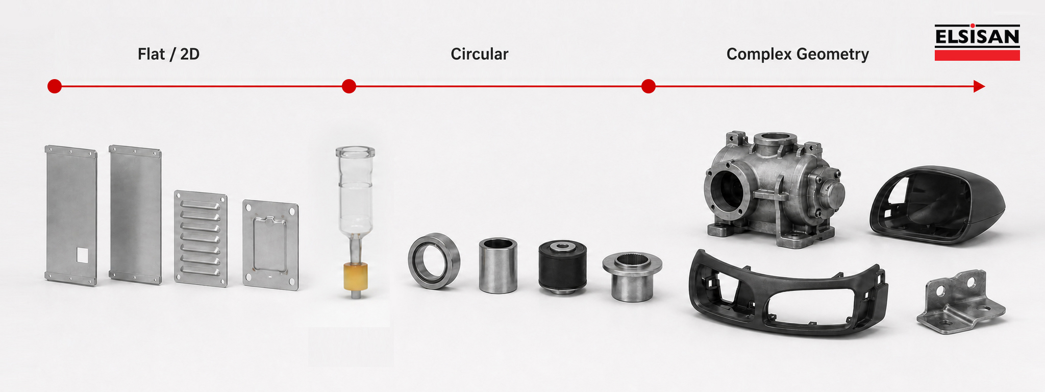
Average product dimensions alone are not sufficient when planning a coating line. The complete product family must be evaluated together, with separate attention given to the largest, heaviest, highest-volume and most difficult-to-coat or handle products. This establishes the correct design limits and allows the equipment to be sized for the actual production requirement.
1.1. Minimum and Maximum Product Dimensions
Product width, length and height directly affect the sizing of the pre-treatment system, coating booth, oven, conveyor route and automatic application zones.
Accurate maximum dimensions are particularly important for defining booth and oven openings, safe spacing between products, conveyor curves and required line clearances. If a product may swing or rotate during transport, this movement must also be included in the design envelope.
1.2. Product Weight and Material
Product weight is a primary input for determining conveyor capacity and hanger or fixture design. On suspended lines, the combined load of the product, hanger, fixture and carrier must be considered. Weight data is also essential for planning safe and ergonomic loading and unloading. Where heavy parts are unsuitable for manual handling, suitable lifting and transfer equipment should be evaluated during the project stage. Correct planning reduces operator workload, improves loading and unloading times and supports stable operation at the target capacity.
Product material is an important factor in defining the pre-treatment and coating process. Steel, aluminium, galvanised steel and other materials can require different cleaning, pre-treatment, drying and coating stages. The material and existing surface condition should therefore be clearly identified at the start of the project.
1.3. Surfaces to Be Coated
The existing surface condition is as important as the substrate material. Oil, corrosion, manufacturing residue or any previous coating should be clearly identified and evaluated when defining the pre-treatment and coating process.
Technical drawings should clearly indicate the areas to be coated, left uncoated, protected or masked. Threaded holes, electrical contact points, assembly surfaces and similar details directly affect gun positioning, application access and masking requirements.
1.4. Hanging Method
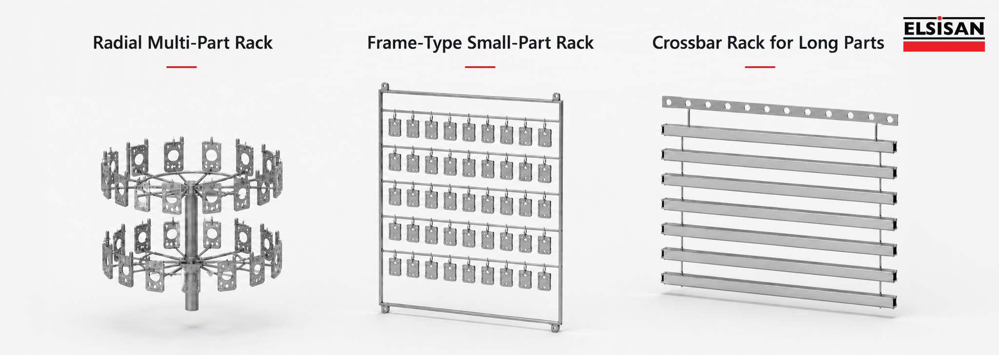
When defining the hanging method, consider the product orientation and direction of travel, suspension points, number of parts per hanger and any need for rotation. The product must remain stable and secure; its centre of gravity, risk of swinging and clearance through booths, ovens and other openings must be reflected in the fixture design.
Marks that may be left by hangers and contact points, and whether those points will remain visible on the finished product, should be evaluated in advance. Where electrical contact is required, its location should be clearly defined in the drawings and hanger design.
If chemical pre-treatment is used, product orientation requires additional consideration. Where the part contains pockets that could retain water or process chemicals, it should be suspended in an orientation that allows liquids to drain freely.
1.5. Preparing a Product Matrix
Instead of evaluating products independently, prepare a product matrix that presents the principal technical data for all product groups together.
The values below are examples only.
| Product Group | Dimensions | Weight | Material | Units per Hour |
|---|---|---|---|---|
| Product A | 500 × 400 × 300 mm | 12 kg | Steel | 80 |
| Product B | 1.200 × 600 × 400 mm | 35 kg | Galvanised Steel | 25 |
| Product C | 800 × 500 × 250 mm | 8 kg | Aluminium | 45 |
The product matrix is used not only to show product diversity, but also to establish the actual design limits of the coating line. Evaluating dimensions, weights, materials and production quantities together makes it easier to determine which product groups should govern the line sizing.
Products with low production volumes but unusually large dimensions or weights should be evaluated separately. Including these parts on the main line can significantly increase booth and oven dimensions, conveyor capacity, line length, energy demand, floor-space requirement and total investment cost.
For example, a plant producing mainly 600 × 400 mm parts may also need to coat a limited number of 3,000 mm products. Sizing the entire system around this exceptional part can create additional capacity with a very low utilisation rate. In such a case, evaluate whether coating that product by a different method outside the main line would be more appropriate technically and economically.
A product matrix helps clarify the following decisions:
- Which product or product group should govern the line dimensions.
- Whether low-volume or exceptional parts can be handled outside the main system.
- Which products have the greatest impact on the investment budget.
- Whether separating the main production line from special-product solutions is technically and economically appropriate.
The objective is not to include every product in the same system, but to define the correct project scope by considering product dimensions, production volumes, technical requirements and investment economics together. This makes it possible to engineer a line that matches the actual production need instead of an oversized system with substantial unused capacity.
At Elsisan, we evaluate product diversity and production targets together from the start of the project to establish a balanced scope in terms of investment cost, energy consumption and operating efficiency.
2. Determine Production Capacity
Coating-line capacity should not be determined from annual production volume alone. Hourly and daily targets, shift pattern, product and colour-change frequency, the share of each product group and planned future capacity increases should be evaluated together.
For conveyorised coating lines, theoretical capacity can be calculated as follows:
Hourly Theoretical Capacity = (Conveyor Speed [m/min] × 60 ÷ Hanger Pitch [m]) × Products per Hanger
Theoretical Capacity Calculator
8 hours/shift · 22 days/month · 12 months/year
The result is theoretical; actual capacity varies with process times, stoppages and product changes.
This value alone does not represent the line’s actual production capacity. Loading and unloading times, operator count, product and colour changes, cleaning, manual touch-up, process waiting times, oven residence time and planned stoppages must also be considered when determining net capacity.
Actual line capacity therefore depends not only on conveyor speed, but on whether all process stages can operate at a compatible production rhythm. Insufficient capacity or a cycle-time mismatch at any stage can create a bottleneck and reduce output below the theoretical capacity.
3. Evaluate Factory Layout and Utilities
Correct placement of the coating line within the factory is as important as selecting the right equipment. A scaled factory layout should therefore be provided before quotation wherever possible.
The layout should clearly show available floor area, ceiling height, columns, doors, access routes, existing machinery and product entry and exit paths. Product flow should be compatible with the existing production arrangement to reduce unnecessary handling distances and internal traffic.
Available electrical power, natural gas, compressed air, process water, wastewater and exhaust connections should also be shared at the start of the project. These inputs support both equipment positioning and the planning of auxiliary systems and connection points.
Layout planning should not focus solely on fitting equipment into the available space. Sufficient access must be retained for safe maintenance and servicing of filters, fans, motors, burners, pumps, conveyors and electrical panels.
If future capacity increases, new products or additional equipment are anticipated, these growth scenarios should also be considered during quotation and engineering.
3.1. Future Capacity Increase and Modular Design
A coating line should be designed around both current production targets and the company’s expected growth. This does not mean oversizing the line during the initial investment.
Correct planning creates a flexible infrastructure that can accommodate an additional booth, more spray guns, conveyor extensions, increased shifts or expansion of selected process sections when required.
At Elsisan, we engineer our lines with a modular design approach that considers future changes and growth. Our in-house panel systems use structures that can be dismantled and reassembled on site instead of welded, permanent joints.
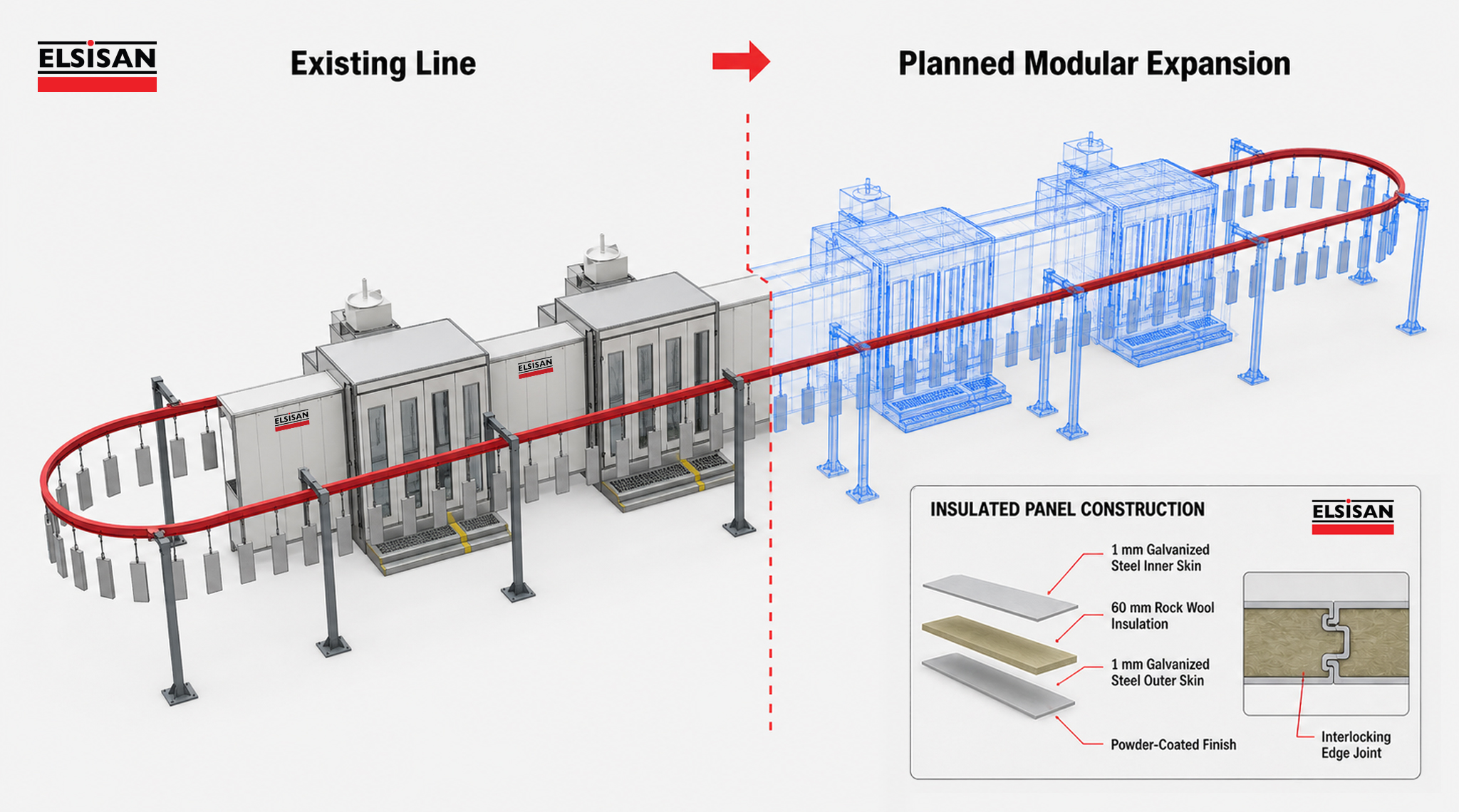
This allows the existing system to adapt to different configurations without complete replacement when capacity increases, product dimensions change or the plant layout must be reorganised. Booths or process sections can be extended, the layout can be revised and existing structures can be repositioned with new equipment in a more controlled manner.
To plan this flexibility correctly, share not only current production volume but also, where possible, the expected growth over the next three to five years, planned new products and potential capacity-increase scenarios. The required infrastructure for later expansion and layout changes can then be anticipated from the start.
4. Select the Coating Application Method
4.1. Manual, Automatic, Robotic and Hybrid Coating Applications
The application method should be selected by considering not only production volume, but also product geometry, part diversity, colour-change frequency, difficult-to-reach surfaces, quality targets and the need for operator intervention.
Manual application can suit projects with high product variety, limited volumes or frequently changing geometries. The operator’s ability to adjust position and technique to the part provides valuable flexibility in low-volume and variable production.
Where products with similar geometries move at a regular production rhythm, automatic spray guns may be used. In automatic applications, the guns can be controlled using vertical gun movers (reciprocators), horizontal in/out positioners, or multi-axis motion systems configured for the product geometry. Product position on the conveyor, spacing, product height, conveyor speed, number of guns and target film thickness directly affect the automation design.
Robotic coating may be considered where complex geometries must be reached repeatably, coating recipes for different products must be stored and high process repeatability is required. Robot selection alone is not sufficient: reach envelope, booth dimensions, paint supply, part handling and positioning, safety equipment and control architecture must be engineered as an integrated system.
Automatic application should not be expected to cover every geometry and surface without support. Manual touch-up may be needed for deep recesses, internal corners, reverse surfaces, weld zones or areas affected by the Faraday cage effect during electrostatic application.
For this reason, many plants use hybrid coating systems rather than exclusively manual or automatic application. Automatic guns coat broad, accessible surfaces while an operator completes complex or difficult areas. This combines the speed, repeatability and transfer efficiency of automation with the geometric flexibility of manual application.
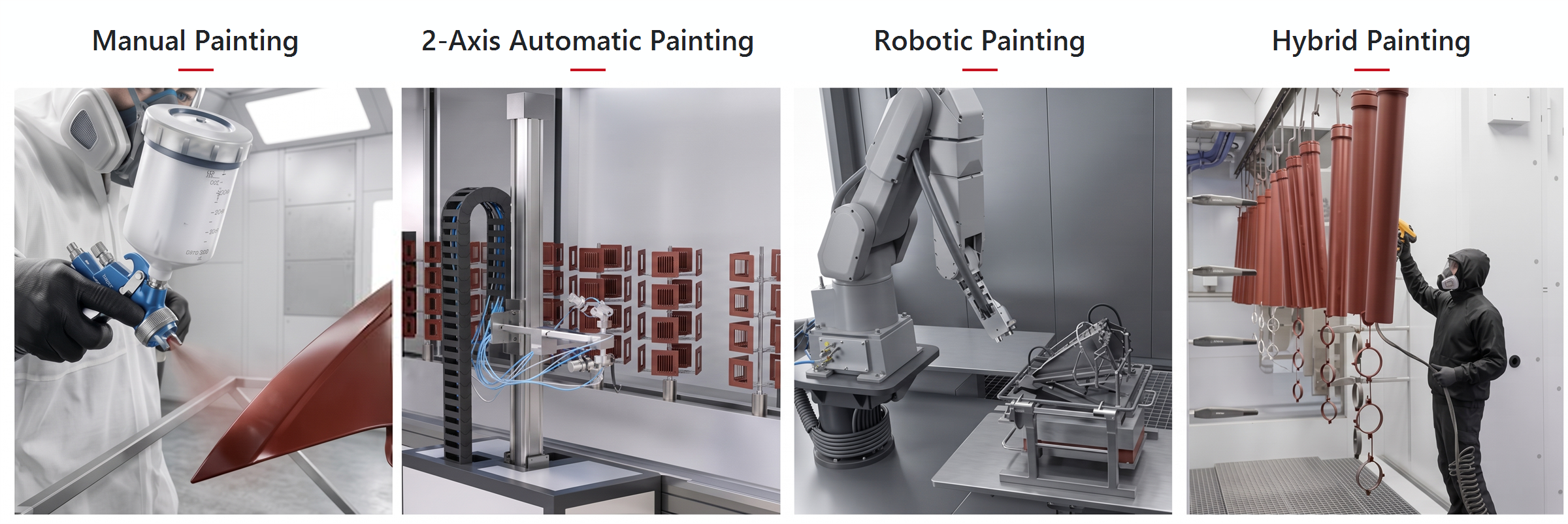
At Elsisan, we develop the application architecture around product geometry, production speed, colour-change frequency and target coating quality. Where required, we plan hybrid systems supported by manual touch-up, gun-moving systems adaptable to different product groups and infrastructure that can accommodate future automation.
5. Define the Process Flow
Once the product characteristics, production capacity and application method have been defined, the process flow can be established.
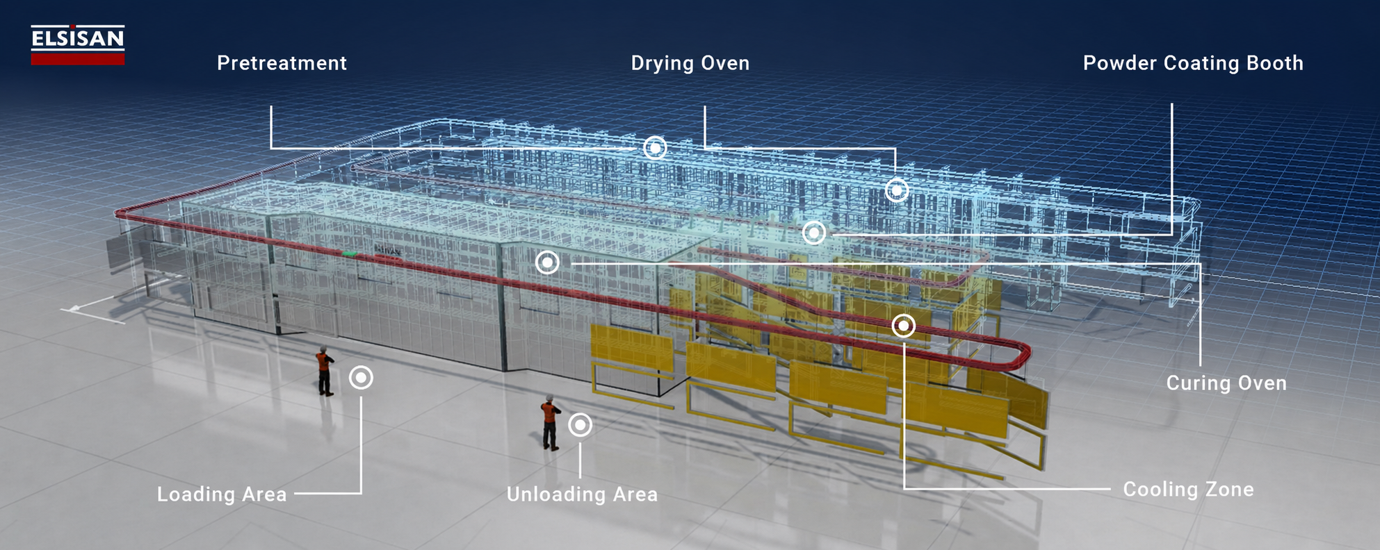
A typical industrial coating line may include the following stages:
- 01 Loading
- 02 Pre-treatment
- 03 Coating Application
- 04 Flash-off
- 05 Drying / Curing
- 06 Cooling
- 07 Unloading
Note: This is an example process sequence. Depending on the coating system and layer structure, pre-treatment may be performed outside the line; coating application, flash-off and intermediate curing stages may be repeated, or some stages may be omitted.
The process sequence may vary according to the coating type and product characteristics.
Where mechanical surface preparation is sufficient, a chemical pre-treatment line may not be required. In liquid-paint systems one or more flash-off zones may be positioned between primer and topcoat applications, or separate booths may be used for different layers. In standard powder-coating applications, the product is generally transferred directly to the curing oven after application, so a separate flash-off process is normally unnecessary.
The process flow should therefore not be copied from a standard template. It must be developed for the project according to the product’s surface condition, coating type and application method, production capacity and quality targets.
6. Select the Right Material Handling System
The material-handling system moves products between pre-treatment, coating, drying, curing and other processes. Its selection therefore directly affects line capacity, layout and process continuity.
The handling system should not be selected from product weight alone. Product dimensions, hanger pitch, line speed, curve radii, elevation changes, loading and unloading times, inter-process accumulation requirements and product positioning must be evaluated together.
Depending on the project and process structure, the following solutions may be considered:
| Handling Systems | Handling Principle | Typical Applications |
|---|---|---|
| Overhead Systems | Products travel on hangers or carriers connected to an overhead conveyor track. | General industrial lines where clear floor space is preferred |
| Floor-Mounted Systems | Products travel on a floor chain, spindle or skid. | Wheels, plastic parts, automotive components and large or heavy products |
| Power-and-Free / Accumulation Systems | Carriers can be stopped, accumulated, separated and moved at different speeds. | Lines requiring different process times, buffers or product routing |
| Dip-Type Handling Systems | Products are immersed in process tanks and transferred to the next station. | Chemical pre-treatment, dip coating and KTL/e-coat processes |
| Manual / Semi-Automatic Handling | Products are moved between stations by operators or simple mechanical equipment. | Low-capacity, batch-type or high-mix plants |
| Special Handling Systems | Project-specific transfer solutions are developed. | Special products and processes not suited to standard handling systems |
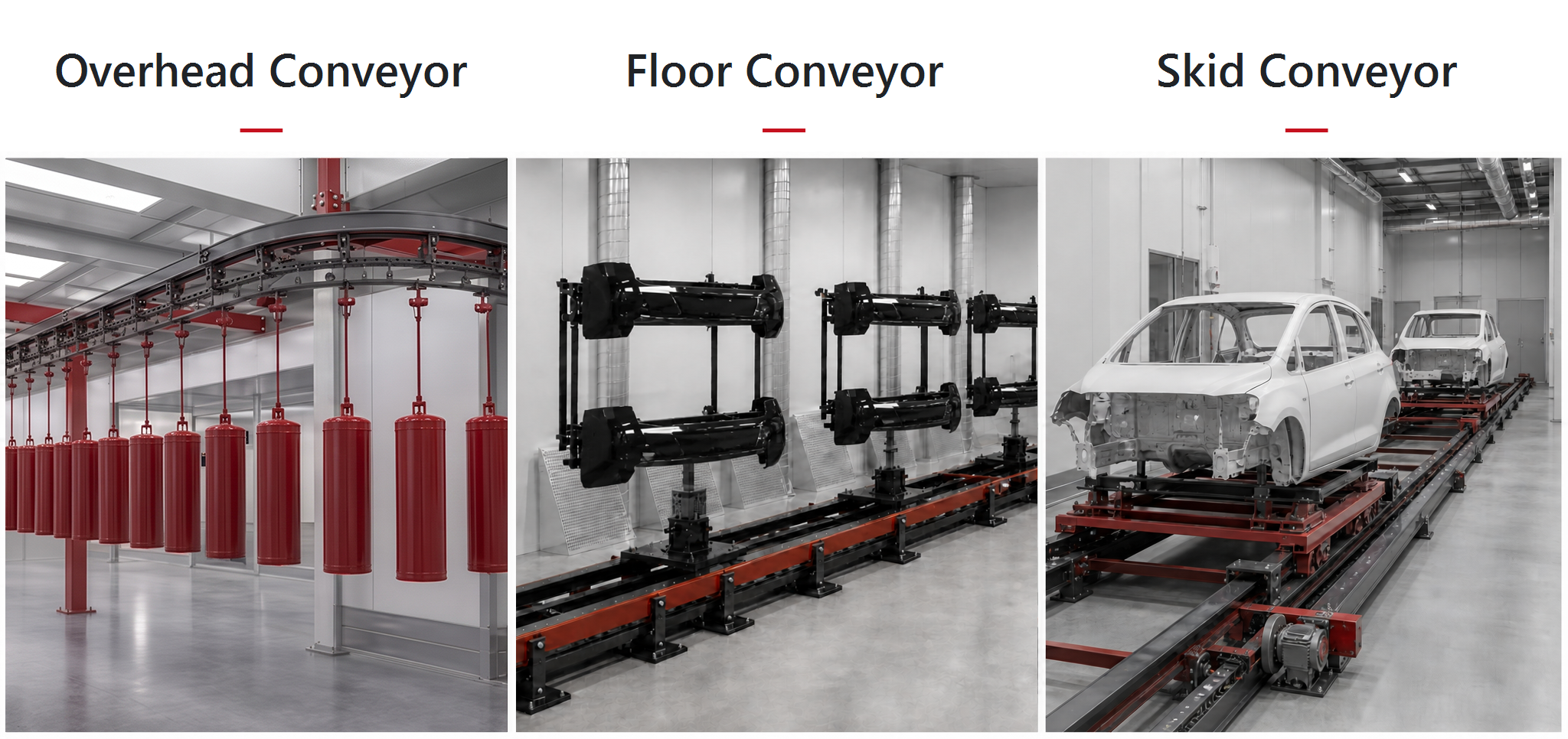
No single handling system is suitable for every coating-line project. The correct solution depends on product characteristics, process structure, production rhythm and future operating scenarios. Proper planning helps balance process times, organise loading and unloading and maintain continuous operation at the target capacity.
7. Main Sections of an Industrial Coating Line
The equipment used in a complete industrial coating line is determined by the product characteristics, production capacity and selected process. Depending on the project scope, the following main systems may be evaluated together.
7.1. Pre-treatment System
Spray pre-treatment lines, dip tanks, enclosed chamber systems, parts washers or mechanical preparation solutions may be used to prepare products for coating. The method is selected according to product material, existing surface condition, required cleanliness and coating-system requirements.
Related content: Pre-treatment Systems
7.2. Coating Booth and Application Equipment
The coating booth is selected according to product dimensions, coating type, application method, production capacity and available workspace. Depending on the project, liquid-paint or powder-coating booths for manual, automatic or robotic application may be integrated with spray guns, reciprocators, robots, paint-supply units, recovery systems and manual touch-up stations.
Related content:
7.3. Drying and Curing Ovens
Water-drying, liquid-paint drying or powder-curing ovens may be used according to the project. Infrared (IR) or ultraviolet (UV) technologies may also be considered where appropriate. Oven selection should be based on product dimensions and weight, hourly load, coating specification, target product temperature, process time, conveyor speed, available space and energy infrastructure.
Related content:
7.4. Ventilation and Air-Conditioning Systems
Ventilation and air-conditioning systems are engineered to maintain the required air quality, temperature and humidity in the booth and related process areas. Supply and exhaust airflow, filtration stages, booth pressure balance, temperature and relative humidity are determined according to the coating type, product characteristics, process requirements and factory environment.
Heating, cooling, dehumidification or humidification may be integrated as required. Correct air conditioning helps maintain coating quality, reduce surface defects and improve process repeatability.
7.5. Energy Efficiency and Heat Recovery
Energy efficiency depends not only on equipment selection, but also on how heat and conditioned process air are managed between processes. Ovens, drying sections, coating booths and air-conditioning systems should therefore be considered together in terms of energy flow.
Depending on the project, hot air from ovens, heat in exhaust air or conditioned process air may be recovered at different points. Where suitable, this energy can preheat fresh air, support another process or reduce total demand. The objective is not merely to choose lower-consumption equipment, but to build a more efficient process by evaluating where energy is generated, used and discharged throughout the plant.
7.6. Automation System
A PLC- and HMI-based automation system enables line equipment to operate under a common process scenario, allows critical parameters to be monitored and provides centralised control. Depending on the project, RFID, barcode or similar identification can track products along the line and automatically call product-specific process recipes. SCADA systems can monitor, record and report process data.
At Elsisan, we engineer the automation architecture around the plant’s control, traceability and efficiency requirements, developing project-specific solutions that integrate mechanical equipment and control systems.
8. Pre-Quotation Information Table
To prepare a technical quotation around actual production conditions, provide the following information using current, measurable data wherever possible.
| Information to Prepare | Details Required for Quotation |
|---|---|
| Product Data | Technical drawings, minimum and maximum dimensions and part weight for each product family. |
| Material and Surface | Material such as steel, aluminium or plastic, plus whether the surface is oily, corroded or pre-treated. |
| Coating and Masking | Marked drawings showing surfaces to be coated and areas to be protected, contacted or masked. |
| Capacity and Growth | Hourly, daily and annual targets, shift pattern and expected capacity increase. |
| Coatings and Chemicals | Powder or liquid coatings and process chemicals, with current technical and safety data sheets where available. |
| Colour Management | Number of active colours, batch size and daily or weekly colour-change frequency. |
| Quality Targets | Film thickness, appearance, adhesion, corrosion resistance and acceptance criteria. |
| Space and Layout | Available net area, ceiling height, column and door positions and preferred product flow. |
| Utilities | Available capacities and connection points for electricity, gas, water, compressed air and exhaust. |
| Automation and Traceability | Requirements for recipe management, data logging, alarms, reporting and ERP/MES integration. |
| Environment and Safety | Applicable environmental conditions, fire scenario, ATEX requirements and worker-exposure conditions. |
8.1. Start the Quotation Process with the Right Data
Share the information already available; missing technical inputs can be clarified together during a preliminary review with the Elsisan engineering team.
Contact us about your project and start the quotation process.